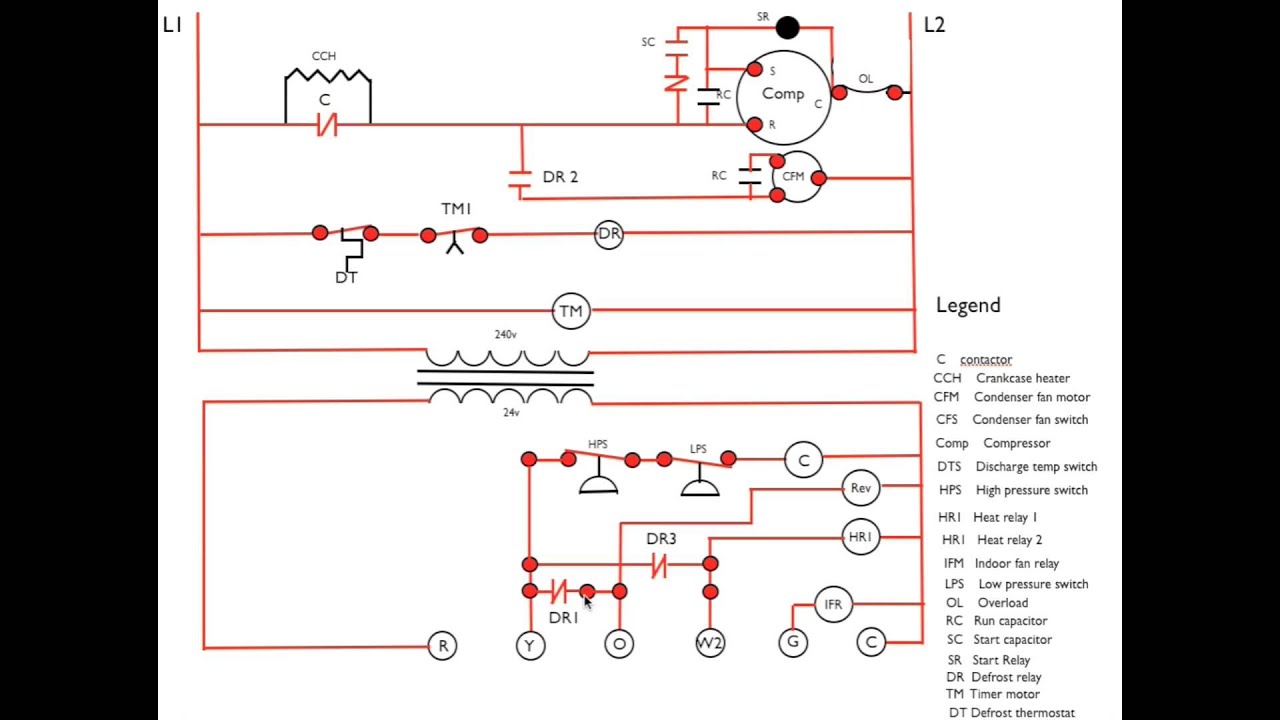
Heat Pump Defrost Board Schematic

Diagram Goodman Heat Pump Defrost Control Board Wiring Diagram Full Version Hd Quality Wiring Diagram Diagramy Pat Pizza Fr

Heat Pump Manual Defrost

Heat Pump Defrost Board Wiring Question Doityourself Com Community Forums
Heat Pump Diagram 3 Call For Defrost Sequence Youtube

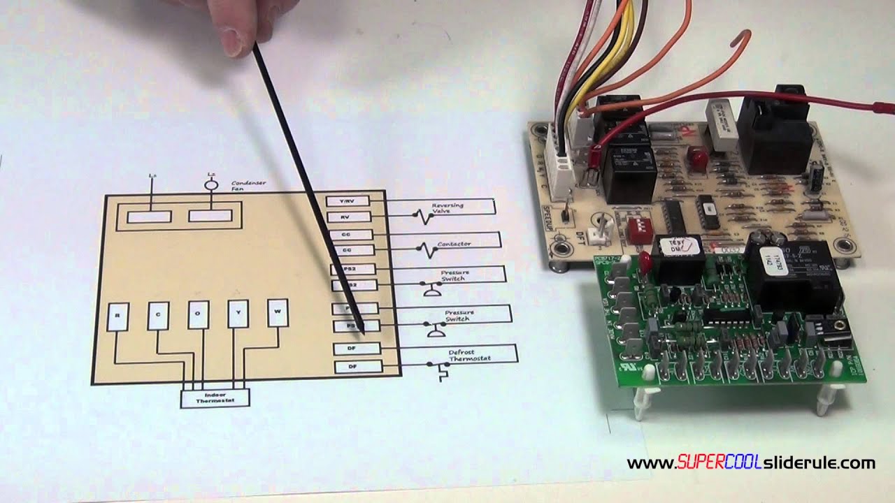
Heat Pump Defrost Control Boards Step By Step
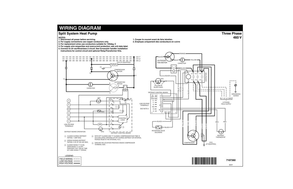
Wiring Diagram Split System Heat Pump Three Phase 460 V Manualzz

York hvac wiring diagrams simple electronic circuits.
Heat pump defrost board schematic.
American Standard Pump Wiring Diagram Diagram Base Website Wiring Diagram Venndiagram Manifestazionipiemonte It

Goettl Heat Pump Wiring And Troubleshooting I Need A Very Experienced Tech Goettl Hp425j With 2 Stage Heat Honeywell

Defrost Cycle No Auxiliary Heat Hvac Diy Chatroom Home Improvement Forum

Cnt05001 American Standard Trane Defrost Control Board
Source : pinterest.com
